The goal of this post is to control a pretty much standard RGB LED strip using a microcontroller. I tried the code below on some PIC16F18855/75 and PIC18F47K42 but should work pretty much the same on any. Originally I implemented that using a Raspberry Pi using this https://dordnung.de/raspberrypi-ledstrip/ tutorial, but now I would like to move in the embedded direction.

We are going to use here a simple RGB LED strip without any controller (e.g. no WS281x or similar). This means that the whole strip always lights with the same color. We are going to use an RGB LED strip but a single color LED strip would work as well. You just need to adapt your configuration to use only one PWM instead of three.
Hardware
Let’s start with the hardware. The strip is basically serial/parallel connection of multiple RGB LEDs.

This gives us 4 wires, one for each color and one for power (12V in my case but can be a different value in yours – implementation indifferent).
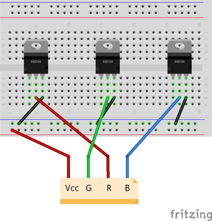
The first thing we need are three N-channel MOSFETs (e.g. IRLZ34N) for controlling the LEDs. In case of a single color LED strip you need just one. You get the idea.
You will power the LED with the 12V power supply and ground each of the colors with the MOSFET. LED which get grounded are going to light up, the others don’t.
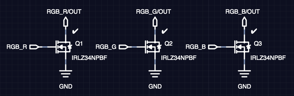
You connect the sources of the MOSFET to the ground, the drains are going to be connected to the LED strip to each color and the gates are going to be connected to our PIC. We will talk about it later.
Microcontroller Configuration
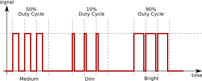
We want our LED strip to allow 1 byte color gradient for each color component. Since LED only are on or off (simplification) we will achieve dimming with on/off pulses. Depending on the on/off ratio on one period the LED will light with different brightness. For that you will need one Pulse Width Modulator (PWM) peripheral per color-component. In case of RGB you will need 3 PWM peripherals for single-color LED you will need only 1 PWM peripheral.
In some cases you PIC may not have enough PWM peripherals. Look also for Capture/Compare/PWM (CCP) peripheral. A CCP combines multiple functionalities and can be also used as a PWM.
A PWM peripheral needs first a timer to define the clock cycle. We can reuse one timer for all 3 PWMs. The timer period should be less than 20ms (50Hz) so the human eye does not catch any flickering. If possible go lower, in my case it proved to be just right around 8ms of timer period – 125Hz (remember those 100Hz TV ads 🙂 )
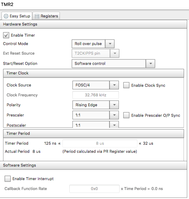
The next step is to configure our PWM/CCP peripherals using this timer.
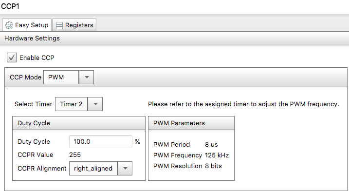
What you want to achieve is that duty cycle of 0% gives a CCPR value of 0 and duty cycle of 100% gives a value 255. Otherwise you will need to do some conversion and may loose some colors. You need to play a bit with the timer period, your PIC frequency to achieve that. My PIC is using a 32MHz Internal Clock and due to some other stuff I have configured there the timer period 8us was just right.
Implementation
Our code relies on some constants to be defined in your program:
- RGB_R_DUTY_CYCLE pointing to CCPR of the PWM for the red color component
- RGB_G_DUTY_CYCLE pointing to CCPR of the PWM for the green color component
- RGB_B_DUTY_CYCLE pointing to CCPR of the PWM for the red color component
If we also want some animations, e.g. blinking, fading-in, fading-out and fade-toggle we need to setup yet another timer which will call our update function. But this is optional.
For brevity I only include the rgb.c source. The full source code can be found at https://github.com/kubovy/mclib/blob/master/modules/rgb.c.
/*
 * File:   rgb.c
 * Author: Jan Kubovy <jan@kubovy.eu>
 */
#include <stdbool.h>
#include <stdint.h>
#include "rgb.h"

#ifdef RGB_ENABLED

uint8_t RGB_redValue;
uint8_t RGB_greenValue;
uint8_t RGB_blueValue;
uint8_t RGB_redTemp;
uint8_t RGB_greenTemp;
uint8_t RGB_blueTemp;
uint8_t RGB_pattern;
uint8_t RGB_delay;
uint8_t RGB_min;
uint8_t RGB_max;
uint8_t RGB_count;

uint16_t RGB_counter = 0;

void RGB_show(void) {
    RGB_R_DUTY_CYCLE = RGB_redTemp;
    RGB_G_DUTY_CYCLE = RGB_greenTemp;
    RGB_B_DUTY_CYCLE = RGB_blueTemp;
}

#ifdef RGB_TIMER_PERIOD
/**
 * Updates LED strip.
 *
 * This should be called periodically by a timer with TIMER_PERIOD period.
 */
void RGB_update(void) {
    uint8_t percent;
    if (RGB_count > 0) switch (RGB_pattern) {
        case RGB_PATTERN_LIGHT:
            percent = 255;
            if (RGB_count < 0xFF) RGB_count--;
            break;
        case RGB_PATTERN_BLINK:
            percent = (RGB_counter / RGB_delay) % 2 ? RGB_max : RGB_min;
            if (RGB_count < 0xFF && percent == 0) RGB_count--;
            break;
        case RGB_PATTERN_FADE_IN:
            percent = (RGB_counter / RGB_delay) % 100;
            if (RGB_count < 0xFF && percent == 99) RGB_count--;
            percent = ((uint16_t) (RGB_max - RGB_min) * percent) / 99  + RGB_min;
            break;
        case RGB_PATTERN_FADE_OUT:
            percent = (RGB_counter / RGB_delay) % 100;
            if (RGB_count < 0xFF && percent == 99) RGB_count--;
            percent = RGB_max - ((uint16_t) (RGB_max - RGB_min) * percent) / 99;
            break;
        case RGB_PATTERN_FADE_TOGGLE:
            percent = (RGB_counter / RGB_delay) % 200;
            if (RGB_count < 0xFF && percent == 199) RGB_count--;
            percent = percent > 100 ? 200 - percent : percent;
            percent = (RGB_max - RGB_min) * percent / 100 + RGB_min;
            break;
    }
    RGB_redTemp = RGB_redValue * percent / 255;
    RGB_greenTemp = RGB_greenValue * percent / 255;
    RGB_blueTemp = RGB_blueValue * percent / 255;
    RGB_show();
    RGB_counter++;
}
#endif

void RGB_off(void) {
    RGB_set(RGB_PATTERN_LIGHT, 0, 0, 0, 0, 0, 0, RGB_INDEFINED);
}

/**
 * Set RGB LED strip configuration.
 *
 * @param pattern Pattern.
 * @param red Red component.
 * @param green Green component.
 * @param blue Blue component.
 * @param delay Delay.
 * @param min Minimum.
 * @param max Maximum.
 * @param count Count.
 */
void RGB_set(uint8_t pattern, uint8_t red, uint8_t green, uint8_t blue,
             uint16_t delay, uint8_t min, uint8_t max, uint8_t count) {
    RGB_pattern = pattern;
    RGB_redValue = red;
    RGB_greenValue = green;
    RGB_blueValue = blue;
    RGB_redTemp = red;
    RGB_greenTemp = green;
    RGB_blueTemp = blue;
#ifdef RGB_TIMER_PERIOD
    RGB_delay = delay / RGB_TIMER_PERIOD;
#endif
    RGB_min = min;
    RGB_max = max;
    RGB_count = count;
#ifndef RGB_TIMER_PERIOD
    RGB_show();
#endif
    RGB_counter = 0;
}

#endif
Conclusion
This implementation using PWM peripherals does not use much processing power of the PIC. The code can be easily adapter do multiple single color strips. The implementation uses c.a. 13 bytes of memory which is due to the animations. Without animations not need any of those. There is still room for improvement which may be an topic for next time. Or look in the Github repo where it may already been optimized: https://github.com/kubovy/mclib/blob/master/modules/rgb.c.
Don’t forget to wire the PWM peripherals outputs to some pins:
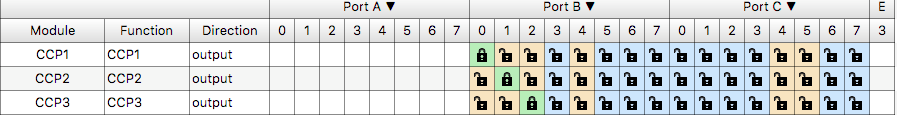
Very nice!
I’ll try that! 😉