In my previous post https://blog.kubovy.eu/2019/02/09/bm78-bluetooth-module-first-glance/ we looked into basics of the BM78 module. Now lets talk about commanding this module in detail.
Operating the BM78 module is done over UART commands send to the module. The module’s response is an asynchronous event also over the same UART interface. For details about the command and event set see: http://ww1.microchip.com/downloads/en/DeviceDoc/IS1678S_UARTCommandSet_UserGuide.pdf.
The BM78 operates in different modes. We can first split those operating modes between Application-Mode and Test-Mode depending on the P2_0, P2_4 and EAN pin configuration. The Application-Mode can be further split between Automatic-Pattern and Manual-Pattern, where the Automatic-Pattern also has an Configuration-Mode.
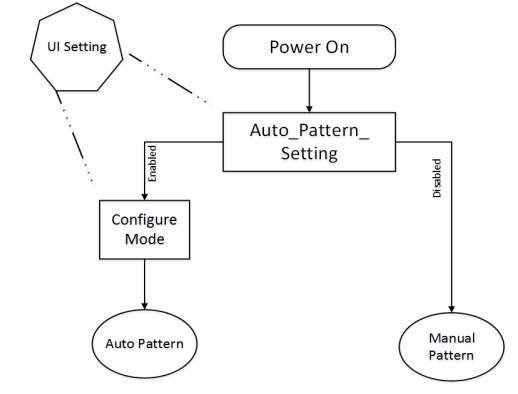
The Test-Mode is meant to update the firmware or the configuration of the BM78 module which cannot be done during runtime. The Application-Mode is meant for normal application. The Automatic-Pattern is meant for simple application with multiple BM78 modules where the BM78 modules builds a simple UART bridge between different devices. In most other applications you will be interested into the Manual-Pattern since this one will give you full control over the BM78 module.
In this post we will only talk about the Application-Mode and only about the Manual-Pattern.
Application mode
The first thing we need to recognize is that the UART communication is asynchronous with some chance of packets being lost. This is important to have in mind when browsing some example on the internet which in their simpleness rely on 100% receive rate and/or kind of a synchronous communication (since we are only sending one command at a time, right?).
In real world application there will be no 100% receive rate and we need to take this into account. Also since the BM78 does not only receives our commands from the PIC but also possibly from bluetooth devices resulting into events, we cannot assume that the only events coming back from the BM78 module are the responses to our commands. It is an asynchronous communication we have to treat it like one.
The full implementation of what we are going to talk in this post can be found at: https://github.com/kubovy/mclib/blob/master/modules/bm78.c. For brevity I only include snippets here, for more context please check the full code.
Sending a command
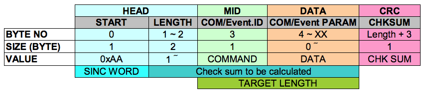
Let’s start with sending a command. A command can be sent using the packet format below over the UART interface. The Command’s ID (or also COM, OpCode) identifies what command is being used. The optional parameters are send in the DATA part. See http://ww1.microchip.com/downloads/en/DeviceDoc/IS1678S_UARTCommandSet_UserGuide.pdf for full list of commands. They are also implemented as BM78_Command_t enum type in https://github.com/kubovy/mclib/blob/master/modules/bm78.h.
I have identified 3 common ways we need a command to be executed:
/**
 * Executes command on the module.
 *
 * @param command Command to execute
 * @param length Length of additional parameters
 * @param ... Additional parameters
 */
void BM78_execute(uint8_t command, uint16_t length, ...);
… to execute simple command with few, fixed arguments;
/**
 * Sends data to the module.
 *
 * @param command Command to use
 * @param length Length of the data
 * @param data Data pointer
 */
void BM78_data(uint8_t command, uint16_t length, uint8_t *data);
… to send arbitrary data using a command; and
/**
 * Writes value to EEPROM.
 * @param command Command to execute.
 * @param store Whether to store or not (BM78_EEPROM_IGNORE/BM78_EEPROM_STORE)
 * @param value Pointer to the value
 */
void BM78_write(uint8_t command, uint8_t store, uint8_t length, uint8_t *value);
… to store configuration to EEPROM (not everything in the BM78 module can be configured using commands).
If we look at the packet format above we can split the command composition into: prepare, data, checksum and commit parts. We will use a common buffer (BM78_buffer in the code) to limit memory use. The common buffer is limiting us to only handle one sending or receiving command at a time.
The prepare part prepares the common part of the command, e.g., sync word, length, command’s OpCode:
inline void BM78_commandPrepareBuffer(uint8_t command, uint16_t length) {
    BM78_counters.idle = 0;               // Reset idle counter
    BM78_state = BM78_STATE_SENDING;
    BM78_clearWriteBuffer();
    BM78_buffer[0] = 0xAA;                // Sync word.
    BM78_buffer[1] = (length + 1) >> 8;   // Length high byte.
    BM78_buffer[2] = (length + 1) & 0xFF; // Length low byte.
    BM78_buffer[3] = command;             // Add command
}
The DATA part will need to be done by each of the 3 functions above. Then we need to calculate the CHKSUM:
inline uint8_t BM78_commandCalculateChecksum(uint8_t length) {
    uint8_t i, chksum = 0;
    for (i = 1; i < (length + 4); i++) { // Add bytes 1-3 (inclusive) to the checksum.
        chksum += BM78_buffer[i];
    }
    return chksum;
}
Last, we actually send the prepared buffer over the UART:
inline void BM78_commandCommit(uint8_t length) {
    BM78_sendPacket(length + 5, BM78_buffer); // Send
    BM78_counters.idle = 0; // Reset idle counter
}

void BM78_sendPacket(uint8_t length, uint8_t *data) {
    uint8_t byte;
    BM78_counters.idle = 0; // Reset idle counter

    while (!BM78_UART_isTXReady()); // Wait till we can start sending.
    // Send the command bits, along with the parameters
    for (int i = 0; i < length; i++) {
        byte = *(data + i);
        // Store each byte in the storePacket into the UART write buffer
        BM78_UART_write(byte);
        while (!BM78_UART_isTXDone()); // Wait until UART TX is done.
    }
    BM78_counters.idle = 0; // Reset idle counter
    BM78_state = BM78_STATE_IDLE;
}
I have a separate BM78_sentPacket function, which we will reuse later on.
This implementation relies on 2 things: First, all async RX UART interrupts are handled by the UART implementation and stored in its own buffer. Second, we always process a full send and full receive separately and both solely from the main loop (not from interrupts!).
Receiving an Event
Now that we can send commands we also want to receive their responses and possibly other events, i.e., the actual bluetooth communication.
As already mentioned above we are relying on an UART implementation using its own RX/TX buffers to balance out any delays caused by processing. What it means is that if our PIC is currently doing something, e.g., sending a command and at the same time something is being received on the UART (possibly bluetooth communication over the BM78 module) this gets stored in the UART’s RX buffer until sending the command is finished. Then in the main loop we always check if there is something on the RX buffer and if so we try to process.
The challenge here is that there may be only a partial command on the buffer at the point of time when we start reading it and the rest will be there when we iterate our main loop one or more additional times. For this purpose we need to introduce some kind of a state preventing us mixing stuff. Remember we are using one common buffer for example. And we would not want to mix our commands with received events there, right?
In the code we are using the BM78_state variable to hold a state of what is going on:
// Single event states
typedef enum {
    BM78_STATE_IDLE = 0x00,

    BM78_EVENT_STATE_LENGTH_HIGH = 0x01,
    BM78_EVENT_STATE_LENGTH_LOW = 0x02,
    BM78_EVENT_STATE_OP_CODE = 0x03,
    BM78_EVENT_STATE_ADDITIONAL = 0x04,

    BM78_COMMAND_RESPONSE_STATE_INIT = 0x81,
    BM78_COMMAND_RESPONSE_STATE_LENGTH = 0x82,
    BM78_COMMAND_RESPONSE_STATE_DATA = 0x83,

    BM78_STATE_SENDING = 0xFF
} BM78_State_t;
The BM78_STATE_IDLE means we can start receiving or sending if we want to, there is currently nothing going on. All “BM78_EVENT_” prefixed states mean that we are at some point of event receiving/processing. All the “BM78_COMMAND_RESPONSE_” prefixed are meant for Test-Mode and will be discussed on a future post. For now it also means we are busy doing something. The “BM78_STATE_SENDING” means we are currently preparing/sending a command.
Note: Sending a command with the above functions does not check the state but simply overwrites it. You have to check the state on your own before calling those functions.
So as mentioned before we will call a function from our main loop (not interrupt!) repeatedly to check for data on the UART’s RX buffer:
/**
 * Checks new data asynchronously.
 *
 * This function should be called periodically.
 */
void BM78_checkNewDataAsync(void) {
    uint8_t byte;

    if (BM78_UART_isRXReady()) {
        BM78_counters.idle = 0; // Reset idle counter
        byte = BM78_UART_read();
        switch (BM78.mode) {
            case BM78_MODE_INIT:
            case BM78_MODE_APP:
                BM78_processByteInAppMode(byte);
                break;
            case BM78_MODE_TEST:
                BM78_processByteInTestMode(byte);
                break;
        }
    }
}
If we want to use a timer, to not to call this function as often, we would need the timer’s interrupt to set some variable and then still call this function from the main-loop. Never call this function from an interrupt! This would first cause a lot of function duplication and may mess things up, since sending data and receiving data, using the same buffer, may get messed up.
We see that this function calls 2 different functions, depending on the mode we are in. The BM78_processByteInAppMode function is then responsible to build the BM78_rx structure depending on the data received over the UART. This is done according to the datasheet:http://ww1.microchip.com/downloads/en/DeviceDoc/IS1678S_UARTCommandSet_UserGuide.pdf. Some examples:
        SYNC|LENGTH|OPC |DATA|CHKS|DESC
COMMAND 0xAA|0x0001|0x02|    |0xYY|Reset
EVENT   0xAA|0x0002|0x81|0x09|0xYY|Idle Mode

        SYNC|LENGTH|OPC |DATA|CHKS|DESC
COMMAND 0xAA|0x0001|0x03|    |0xYY|Read status
EVENT   0xAA|0x0002|0x81|0x09|0xYY|Idle Mode
Check the BM78_Response_t, BM78_CommanddOpCode_t and BM78_EventOpCode_t to see the different possible response structures and codes in https://github.com/kubovy/mclib/blob/master/modules/bm78.h.
Checking the UART’s RX buffer goes:
- so long till it finds the 0xAA sync word. Then it changes the BM78_state to BM78_EVENT_STATE_LENGTH_HIGH.
- The next byte read on the UART’s RX buffer is used as the high byte of BM78_rx.response.length and changes the BM78_state to BM78_EVENT_STATE_LENGTH_LOW.
- Than the next byte read on the UART’s RX buffer writes the low byte of BM78_rx.response.length and changes the BM78_state to BM78_EVENT_STATE_OP_CODE.
- The next byte on the UART’s RX buffer sets the BM78_rx.response.op_code and changes the BM78_state to BM78_EVENT_STATE_ADDITIONAL.
- From there the processing differs depending on the command’s OpCode (check https://github.com/kubovy/mclib/blob/master/modules/bm78.c for further details).
- Then the processing is finished or fails at any point the BM78_state must be set back to BM78_STATE_IDLE.
I also implement to callback handlers for the event processing:
- BM78_AsyncEventResponse called when an event was received successfully, and
- BM78_ErrorHandler called when something wrong happened during the event processing.
The BM78_AsyncEventResponse is not exposed but does some internal stuff (see below) and exposes:
- BM78_TransparentDataHandler called when data were received from a bluetooth device, and
- BM78_ErrorHandler called when something wrong happened on this higher level of processing.
Default AsyncEventResponse Handler
The BM78 implementations considers 3 modes: Application-Mode (BM78_MODE_APP) and Test-Mode (BM78_MODE_TEST) of the BM78 and additionally an Initialization-Mode (BM78_MODE_INIT). As we discussed the BM78 enters by default the Application-Mode, but our implementation considers calls it the Initialization-Mode, a virtual sub-mode of the Application-Mode. In this mode we try to check and setup some basics, e.g., device’s name, pairing mode and pin. Then the initialization is done the the BM78 will transit from BM78_STATUS_IDLE_MODE (0x09) to BM78_STATUS_STANDBY_MODE (0x03) state using the following command:
SYNC|LENGTH|INVISIBLE_SETTING|STANDBY_MODE_ENTER|CRC |
0xAA|0x0002|0x1C             |0x01              |0xYY|
Then the BM78.mode will be actually be set to BM78_MODE_APP.
The default BM78_AsyncEventResponse handles then the events listed bellow. Additionally if BM78_ResponseHandler is defined all responses will be also passed to that handler after they are process by the default handler. This enables custom handler implementation in your application.
BM78_EVENT_LE_CONNECTION_COMPLETE (0x71)
Any ongoing or scheduled transmission is cancelled. New connection, new communication.
BM78_EVENT_DISCONNECTION_COMPLETE (0x72)
BM78_EVENT_DISCONNECTION_COMPLETE (0x72) received from the BM78 module when a connected bluetooth devices gets disconnected. In Manual-Mode the BM78 enters back to the BM78_STATUS_IDLE_MODE state.
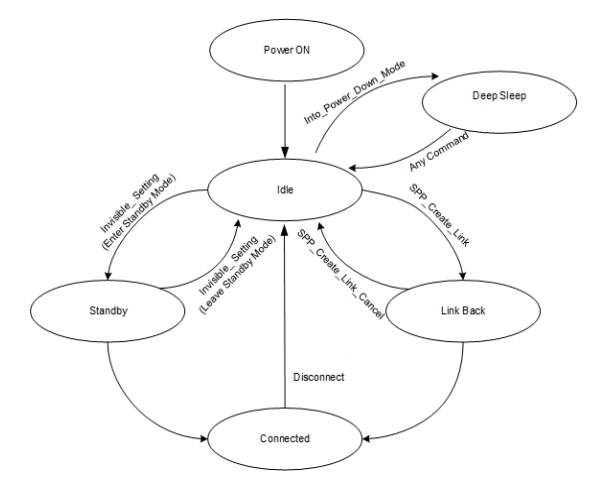
In this state no bluetooth device can connect to the BM78 module until it manually enters the BM78_STATUS_STANDBY_MODE state. The handler will send a command:
SYNC|LENGTH|INVISIBLE_SETTING|STANDBY_MODE_ENTER|CRC |
0xAA|0x0002|0x1C             |0x01              |0xYY|
to enter the BM78_STATUS_STANDBY_MODE state. Additionally any ongoing or scheduled transmission is cancelled.
BM78_EVENT_SPP_CONNECTION_COMPLETE (0x74)
Any ongoing or scheduled transmission is cancelled. New connection, new communication.
BM78_EVENT_COMMAND_COMPLETE (0x80)
Checks the response to one of the following command:
- BM78_CMD_READ_DEVICE_NAME (0x07) will write the device’s name to BM78.deviceName and where the rest of the program can access it.
- BM78_CMD_READ_PAIRING_MODE_SETTING (0x0A) and
- BM78_CMD_WRITE_PAIRING_MODE_SETTING (0x0B), both above event responses will write the read or written pairing setting to BM78.pairingMode where it can be accessed by the rest of the program (see BM78_PairingMode_t for the different options).
- BM78_CMD_READ_ALL_PAIRED_DEVICE_INFO (0x0C) will store all paired device MAC addresses to BM78.pairedDevices where it can be accessed by the rest of the program.
- BM78_CMD_DISCONNECT (0x1B) will request re-entering the BM78_STATUS_STANDBY_MODE state.
- BM78_CMD_READ_PIN_CODE (0x50) will store the PIN number to BM78.pin where it can be accessed by the rest of the program.
- BM78_CMD_WRITE_PIN_CODE (0x51) will fire BM78_CMD_READ_PIN_CODE command to refresh the BM78.pin variable.
BM78_EVENT_BM77_STATUS_REPORT (0x81)
Will check the response containing the current BM78 status and in case of:
- BM78_STATUS_STANDBY_MODE (0x03) or
- BM78_STATUS_LINK_BACK_MODE (0x04) it will abort any ongoing or scheduled transmission.
- BM78_STATUS_IDLE_MODE it will request re-entering the BM78_STATUS_STANDBY_MODE state.
BM78_EVENT_RECEIVED_TRANSPARENT_DATA (0x9A)
also another BM78_EVENT_RECEIVED_SPP_DATA (0x9B) is defined for the same thing, since the OpCode 0x9A is not somehow implemented in my BM78 but I found out that the OpCode 0x9B is used instead.
In this layer I implemented my own protocol which puts a checksum on the beginning of the data packet as the 1st byte. The 2nd byte contains type of the message. On this level we only are concerned about message type BM78_MESSAGE_KIND_CRC. Any other message type will be forwarded using the BM78_TransparentDataHandler.
First we check if the checksum in the 1st byte corresponds with the actual message. We only consider correctly received messages further.
Next, if the message type is BM78_MESSAGE_KIND_CRC we update BM78_tx.chksumReceived for further processing. Any other message type gets passed to the BM78_TransparentDataHandler and a BM78_MESSAGE_KIND_CRC message gets send back to the sender as a confirmation.
Conclustion
This is my implementation for the BM78 module please check out the https://github.com/kubovy/mclib/blob/master/modules/bm78.c.