Goal/Use case
Let’s build a kind of a bigger gadget to deploy applications. This Deployment Football (Suitcase) will configure our monitor application, which then will be able to perform different tasks, e.g. deployment of a software by triggering Jenkins, Bamboo or other CI/CD software.
Hardware

We want everything to fit a standard-sized tool suitcase. We need to create a fake bottom with proper holes to put our buttons, LEDs, etc. in. For this purpose we used an acrylic glass 500×500 and we cut it to match the inner size of the suit case.
Cutting an acrylic glass is very similar to cutting a normal glass. Just instead of a glass cutter you can use a normal utility knife. It is good to fixate some ruler or straight wood and cut multiple times to make the cut a bit deeper. After making the cut we’ve fixated the acrylic glass on a tablet in a way that the cut is precisely on the table’s edge and fixated on the whole width. Then you just need a swift push up or down and the glass should break exactly on the cut. There are better and more precise ways and tools to cut acrylic glass if you need smooth edges but our edges will be hidden and protected inside the suitcase – so we chose the simplest, cheapest way.
The next challenge was drilling the wholes. We needed 2 runs, the first glass broke during drilling and here are some tips we’ve found out, so you don’t have to repeat our mistakes:
Tip 1: Fixate the acrylic glass during drilling. An unfixed glass will in the instance of drilling through twitch, giving the driller an opportunity to cut deeper on a side and break the glass.
Tip 2: Drill with slow RPM. The slower the better. We used a normal electric driller for walls, iron and wood use and the result was not that good. Later we switched to a smaller battery driller with way smaller RPM which proved to be much more precise. Also with higher RPM the acrylic glass may start to melt.
Tip 3: Do not use drillers for wood. Either buy special drillers for glass, acrylic glass, etc. or if you are really desperate use drillers for iron. The thing is that wood drillers are much more sharp and tend to cut into the edges, especially when you drill through.
Then the fun part started, the electronics.
Parts
- Raspberry Pi Zero W (W for wireless – wifi, bluetooth)
- 2x MCP23017-E/SP 16 I/O Expander with DIP28 I2C (Amazon) – we need a lot of IOs, the Raspberry doesn’t have enough
- 1x Sunflower Rounder IIC/I2 °C/TWI Serial 2004 20×4 LCD (Amazon)
- 1x Cylewet 100 2 Channel Logic Level Converter 3.3 V To 5 V TTL CLW1070 (Amazon) – for the LCD above
- 50PCS WS2811 RGB Full Color 12mm Pixels digital Addressable LED String DC 5V (Amazon)
- 3x Secured switches with LED indicator, e.g. Hot System 2x 12 V 20 A Car Switch SPST Rocker Switch On/Off Switch LED Indicator Switch, red (Amazon)
- 18x normal switches, e.g. Art Gear Toggle Switch 250 V 6 A/125 V 10 A ON/OFF Rocker Switch, Spst 2 Pin Metal Rocker Toggle Switch for Car Boat Pack of 6, Black) (Amazon)
- 1x Push button with LED indicator, e.g. Hot System 16 mm 12 V Rustproof Metal LED Illuminated Push Button Switch Pressure Switch Push Button On/Off Switch (Amazon)
- 2x Key switch, e.g., Sourcingmap AC 400 V 10 A NC NO DPST 2 Positions Locking Selector Rotary Switch w 2 Keys (Amazon)
- 1x Rotary switch, e.g. 19 mm, 4 Pin, 2 x Stainless Steel Opener, 250 V/6 A, S127 (Amazon)
- Some other stuff like memory card, acrylic glass, tool suitcase, embosser, embossing tape and some branding stickers
Step 1: Provisioning
So first we provisioned our Raspberry Pi Zero W and installed our control program. This program allows essentially to control the raspberry via MQTT and other interfaces.
Step 2: LED Indicators
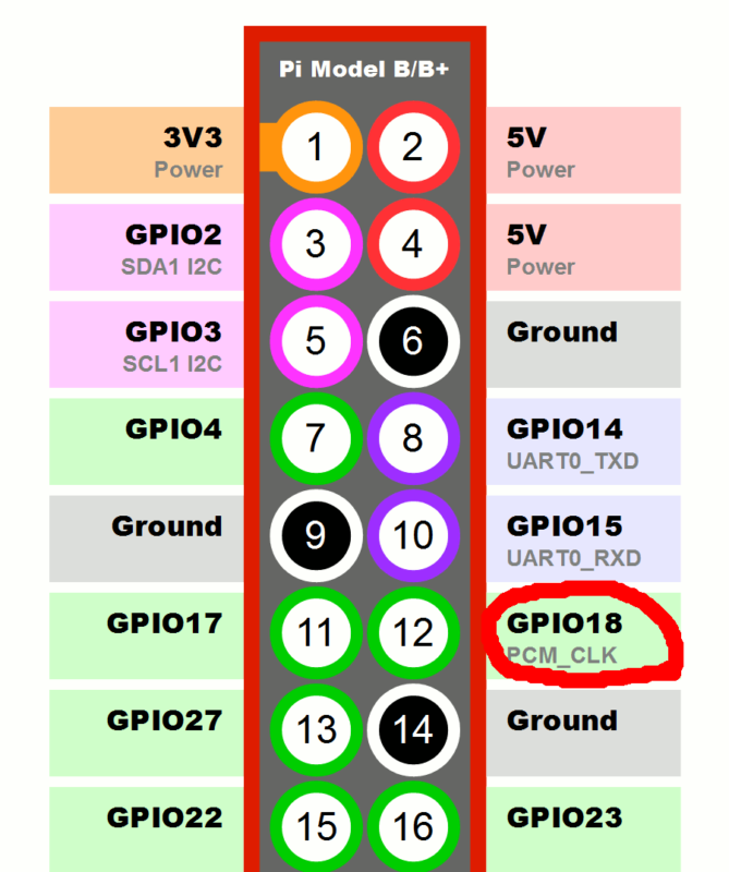
This step was naturally the next since we already did a project on that matter. We are again using a WS281x LED strip, allowing us to control each light separately. The only pin on the Raspberry Pi we need for that is the GPIO18 (pin 12). Since the use case is a bit different from the Status Light, there is a special module (WS281xIndicators) for that purpose. This module differs from the WS281x module that it is focused on a state and not on a pattern – each light has now a separate state. The looper then updates all the lights at once.
Step 2: LCD
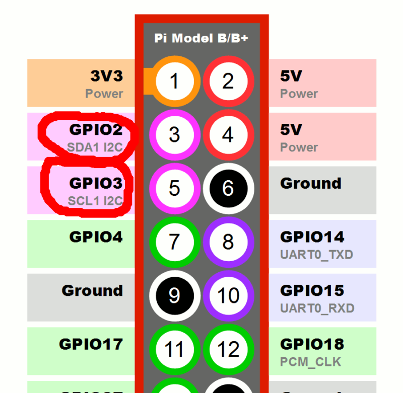
The next thing was to connect the LCD. This is done using the I2C protocol on pins GPIO2 (pin 3) and GPIO3 (pin 5) on the Raspberry PI. Since the LCD is using a 5V logic and the Raspberry Pi a 3V logic we need a converter between them. This is in our case the Cylewet 100 2 Channel Logic Level Converter 3.3 V To 5 V TTL CLW1070 from the list above. The LCD is also integrated using a module in our control program. The LCD will run on the I2C bus with the address 0x27 (configurable).

Step 3: Extending inputs and outputs
Our suitcase should have 23 switches (18 normal switches, 3 protected switches and 2 key switches), 1 rotary switch with 3 positions a push button and additionally 4 LED indicators embedded in some of the switches. This gives us a total number of 25 required inputs and 4 required outputs (29 IOs in total). The Raspberry’s GPIO does not provide that many. Therfore we use two MCP23017-E/SP 16 I/O each providing 16 IOs. With some reserve we have now 32 IOs.
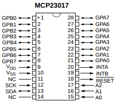
This chip communicates as the LCD on the I2C bus and our chips use addresses 0x20 and 0x21. The integration to the system is done using MCP23017 module. The inputs and outputs need to be decided before, the inputs need a discharging resistor and the outputs need a serial resistor for the LEDs. In our case: both, GPA and GPB on chip 1 (address 0x20) will be inputs. On chip 2 (address 0x20) GPA and GPB0-GPB2 will be all inputs, GPB3-GPB7 will be outputs.
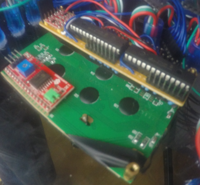
We solider the 2 DIP sockets for the 2 MCP23017 chips with the 2 Channel Logic Level Converter on one PCB. This PCB has the same width as the LCD board so it can be easily mounted under it.
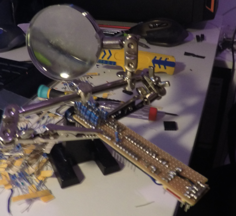
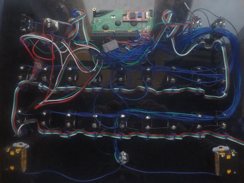
Step 4: Wiring
The wiring was a bit of a challenge. You can judge the result on your own:
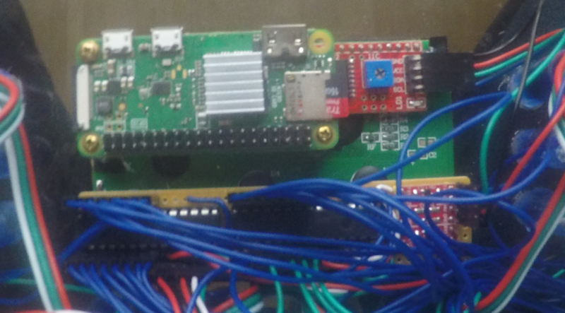
Step 5: Putting all together
Almost there. Now what we need is to connect the Raspberry Pi with the WS281x light strip, with the IO extender, the LCD and connect all the switches, buttons and LEDs to the MCP23017 pins.
Software
As mentioned there are new modules added to the Raspberry Project. For the WS281x Indicators, the MCP23017, the LCD display, the Bluetooth and the State Machine.
WS281x Indicators module
The WS281x Indicators is based on the WS281x module with the difference that the focus is now on a state and not on a pattern. The interesting part is the looper method which sets the color of all the LEDs based on their state. Some simple patterns per LED are supported, e.g., fade and fadeToggle. This module is able to listen for MQTT messages, serial communication or be updated directly using the set method, which is how we use this module in this case. The payload of this method takes a JSON which has the similar format as in the WS281x module:
{
  "pattern": "light",
  "color": {
    "red": 255,
    "gree": 0,
    "blue": 0
  },
  "wait": 50,
  "min": 0,
  "max": 100
}
MCP23017 module
Next is the MCP23017 module. This module listens for MQTT messages or can be controlled directly using the get, get_all, set and write_all methods. Again we are using it directly in our case. This module also contains a looper which checks all inputs and sets all outputs periodically.
The MCP23017 communicates over the I2C protocol which needs to be enabled on the Raspberry Pi. Once the I2C interface is enabled and connected to the hardware we can double check the wiring.
pi@mitrula ~ $ sudo i2cdetect -y 0
     0  1  2  3  4  5  6  7  8  9  a  b  c  d  e  f
00:          -- -- -- -- -- -- -- -- -- -- -- -- --
10: -- -- -- -- -- -- -- -- -- -- -- -- -- -- -- --
20: 20 21 -- -- -- -- -- 27 -- -- -- -- -- -- -- --
30: -- -- -- -- -- -- -- -- -- -- -- -- -- -- -- --
40: -- -- -- -- -- -- -- -- -- -- -- -- -- -- -- --
50: -- -- -- -- -- -- -- -- -- -- -- -- -- -- -- --
60: -- -- -- -- -- -- -- -- -- -- -- -- -- -- -- --
70: -- -- -- -- -- -- -- --
The addresses 0x20 and 0x21 are the MCP23017 expanders and the 0x27 is the LCD (see below).
LCD module
As mentioned above also the LCD is controlled by its own module. It listens to MQTT messages, Bluetooth communication, serial communication and can also be controlled directly using the post method. In our use case we are controlling it mostly directly with one exception and that is the LCD reset command over Bluetooth which can be sent by the monitor application. The module uses a message queue what to display and an internal looper to prevent concurrent changes which may mess up the display. This way all messages are displayed after each other without blocking the parent thread sending the request to display a message on the LCD.
State Machine module
Another module from the Raspberry Project, putting all the things together, is a State Machine module. This module loads a description file, which contains all the states, conditions, expressions and actions available in each state. A sample description file can be looked up here.
Each state is identified by a name. The basic idea of a state here is a list of conditions. Each condition can have zero to multiple expressions and one to multiple actions. All expressions and all actions in one condition with a logical AND. This means that only if all of the expressions in a condition are evaluated as true all the actions in that condition will be executed.
After initialization the state machine transits to the initial state (initial state is the first state in the description file. From there it depends on the conditions what happens next.
Transition from one state to another (or to an initial state) goes thru 4 stages. First stage is so called enter stage. In this stage only conditions without any expressions will be considered, triggering all the actions in such conditions. Conditions without expressions are so called entering state actions.
The next stage is initializing and after comes the initialized stage. Both work the same. They evaluate all the conditions with expressions and trigger the corresponding actions, if all expressions evaluate to true. Exiting the initialized stage means the state transition was successful and the state machine is in a stable stage entering the normal stage of the new state.
The normal stage works similar to the initializing and initialized stage with the difference that not only all expressions in a condition must evaluate to true but also that at least one expression in that condition must change its evaluation, i.e., a change must have happened.
From the data point of view an expression and an action are the same. They are defined as an object with 3 attributes: kind, key and value. Kind is identifying a module, key is a value identifier and value is the content. Example:
{ kind: mcp27013, key: 2, value: True }In case of an expression the value is the thing to be evaluated and in case of action the value is to be set.
To make things a little bit easier to read and write a list of devices may be defined in the definition file. A device is basically a combination of a kind and a key. Such device can be then used in expressions or actions using name:
devices:
  - btn_2: { kind: mcp23017, key: 2 }
...
- name: "some-state"
  conditions:
    - expressions:
      - { name: btn_2, value: True }
...
A condition, expression or action may be limited to only a certain stage. This can be achieved by adding the attribute only to the condition, expression or action with the name of stage (initializing, initialized, normal).
The value can also contain Jinja2 templates. To tell the state machine that a value needs to be evaluated with Jinja2 an additional attribute eval needs to be set to true on the corresponding expression or action. Also for more complex, repeated data structures variables may be defined in the definition file. Those will be put into the Jinja2 context for template evaluation.
Bluetooth module
Last but not least there is a Bluetooth module allowing to communicate with the monitor application. This way we can easily configure what and how can be triggered with this gadget. The Bluetooth module allows a special value “DUMP” which sends all the configuration over Bluetooth to the monitor application. There it can be used to configure and trigger some other services.