To enable interaction with the environment our project will need some kind of communication interface. After some research we decided to go with Bluetooth. A nice comparison can be seen in the video below starting at 8:20.
To summarize:
| Tech. | Band | Data Rate | Topology | Power | Phone Support |
| Bluetooth | 2.4GHz | up to 2MHz | Mesh (w/ BT5) | Low (BLE) | Yes |
| Thread | 2.4GHz | 250 kbps | Mesh | Low | No |
| WiFi | 2.4GHz, 5GHz | up to 1Gbps | Limited mesh | High | Yes |
| Z-Wave | Sub-GHz | 100kbps | Mesh | Low | No |
| ZigBee | 915MHz-2.4GHz | 250 kbps | Mesh | Low | No |
After searching for a viable bluetooth module with BLE, Bluetooth 5 support and also classic SPP the BM78 module from Microchip came up. Full datasheet can be looked up at http://ww1.microchip.com/downloads/enDeviceDoc/60001380A.pdf.
Microchip also provides a prototyping/development HW https://www.microchip.com/DevelopmentTools/ProductDetails/BM-78-PICTAIL.
Basic wiring
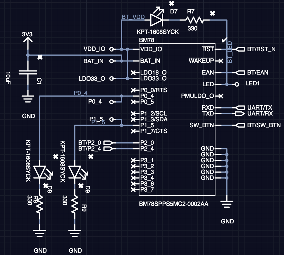
The module needs at least the BAT_IN, GND, SW_BTN, P2_0, P2_4, EAN, UART_RX and UART_TX pins to be connected to a microcontroller in order it to be operational. A simple connection example:
| Symbol | Type | Description |
| BAT_IN | Power | Battery Input (3.3V to 4.2V) Main positive supply input Connect to 10 uF (X5R/X7R) capacitor |
| SW_BTN | DI | Software Button H: Power On, L: Power Off |
| LDO33_O | Power | Internal 3.3V LDO output, can source no more than 50 mA |
Internal use only, N/C | ||
| WAKEUP | DI | Wakeup from Sleep mode (active- low, internal pull-up) |
| Power | ||
| P0_4 | DO | Status 1 indication pin / UART_TX_IND (DO) |
| P1_5 | DO | Status 2 indication pin. |
| P2_0 | DI | System configuration pin. |
| P2_4 | DI | System configuration pin. |
| EAN | DI | System configuration pin. |
| RTS_N | DI | Module reset (active-low, internal pull-up) |
| RXD | DI | UART data input |
| TXD | DO | UART data output |
(Internally pulled-up, if configured as an input) Default: INQUIRY_CONTROL | ||
| P3_2 | DIO | Configurable control or indication pin (Internally pulled-up, if configured as an input) Default: DISCONNECT (DI) |
(Internally pulled-up, if configured as an input) Default: UART_RX_IND (DI) | ||
(Internally pulled-up, if configured as an input) Default: PAIRING_KEY | ||
(Internally pulled-up, if configured as an input) Default: N/C | ||
(Internally pulled-up, if configured as an input) Default: LOW_BATTERY_IND | ||
| LED1 | DO | Status LED, connect to LDO33_O |
| GND | Power | Ground reference |
The bolded symbols are necessary to operate the BM78 module. The striked-through will not be used un our examples, should not be used, or are only for internal use. The rest is optional. For details consult the datasheet mentioned above.
Operation
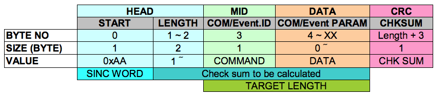
Operating the BM78 module is done over UART commands send to the module. The module response is an asynchronous event also over the same UART interface (http://ww1.microchip.com/downloads/en/DeviceDoc/IS1678S_UARTCommandSet_UserGuide.pdf).
By default the BM78 operates in so called Auto-Mode. This mode is meant to easily hook-up 2 BM78 modules and create a simple UART bridge between 2 devices using those same modules. For other applications the other, Manual-Mode, needs to be configured. This is the biggest obstacle when starting with this module. For this the module needs to be reconfigured in its flash memory. There are 2 ways how to achieve that. First is with the provided UI tool. This can be easily done if you are using the BM78 PICTAIL since it has a UART/USB converter and a USB interface. More you move to embedded devices you may not want to always integrate a UART/USB converter to “just” setup the BM78 module.
Configuring the BM78
After a lot of googling and lot of trying out we found out that the most feasible way is to make the configuration with the UI tool, export the configuration, transform it to C code and load it into our PIC project where it gets executed. I wrote a converter for for that: [TODO share link to repo]. The resulting C code looks like:
typedef struct {
    uint16_t address;  // Address
    uint8_t  length;   // Packet length
    uint8_t  data[32]; // Data (max. 32 bytes per packet)
} Flash32_t;

const Flash32_t BM78_configuration[48] = {
    0x0007, 0x03, {0x80,0x28,0x10,0xFF,0xFF,0xFF,0xFF,0xFF,
                   0xFF,0xFF,0xFF,0xFF,0xFF,0xFF,0xFF,0xFF,
                   0xFF,0xFF,0xFF,0xFF,0xFF,0xFF,0xFF,0xFF,
                   0xFF,0xFF,0xFF,0xFF,0xFF,0xFF,0xFF,0xFF},
    0x000B, 0x20, {0x4E,0x75,0x6B,0x6C,0x65,0x61,0x72,0x20,
                   0x46,0x6F,0x6F,0x74,0x62,0x61,0x6C,0x6C,
                   0x00,0x00,0x00,0x00,0x00,0x00,0x00,0x00,
                   0x00,0x00,0x00,0x00,0x00,0x00,0x00,0x00},
    //...
};
To save memory we only record packets which needs to be changed. Thus the Flash32_t type.
After powering up the BM78 module it goes to a mode depending on the P2_0, P2_4 and EAN pin configuration:
| P2_0 | P2_4 | EAN | Operation Mode |
| Low | Low | High | Write FLASH |
| Low | High | Low | Write EEPROM (Test-Mode) |
| High | High | Low | Normal operation (Application-Mode) |
We are considering here only the Flash variant BM78SPPx5MC2 here.
To switch between the Application-Mode and the Test-Mode we use the following:
void BM78_clear() {
    // Clear any state neccessary
}

void BM78_reset(void) {
    BM78_clear();
    BM78_RST_N_SetLow();  // Set the reset pin low
    __delay_ms(2);        // A reset pulse must be greater than 1ms
    BM78_RST_N_SetHigh(); // Pull the reset pin back up
}

void BM78_resetMode(void) {
    BM78_reset();    // Reset the device
    __delay_ms(100); // Wait a minimum of 24 seconds for mode to be detected
}

void BM78_resetToTestMode(void) {
    BM78.mode = BM78_MODE_TEST;

    BM78_power(false);
    __delay_ms(200);
    BM78_power(true);
    __delay_ms(200);
    BM78_reset();
    __delay_ms(200);

    BM78_P2_0_SetLow();
    BM78_P2_4_SetHigh();
    BM78_EAN_SetLow();
    BM78_resetMode();
}

void BM78_resetToAppMode(void) {
    BM78.mode = BM78_MODE_INIT;

    BM78_P2_0_SetHigh();
    BM78_P2_4_SetHigh();
    BM78_EAN_SetLow();
    BM78_resetMode();
}
The program relies on the following pin configuration of the PIC:
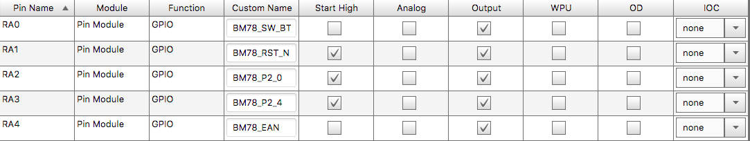
Notice the “Start High” configuration for BM78_P2_0, BM78_P2_4 and BM78_EAN putting the BM78 module into Application-Mode after powering up. The common “BM78_” prefix used in the pin names is a convention used further in the code.
Then we need to send the BM78_configuration array to the BM78 module over the UART interface. An implementation of that can be found in the MCLIB.
Prototyping with BM78-PICTAIL
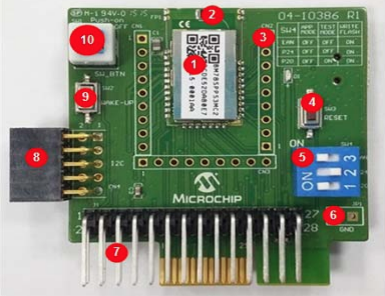
This board allows fast prototyping and finding stuff out missing or buried deep in the datasheets. IMHO you will have a very hard time starting with BM78 without this PICTAIL since I had to find a lot of stuff out by try-fail approach since not everything can be found in listed datasheets.
The most important 2 schematics is the module’s test interface:
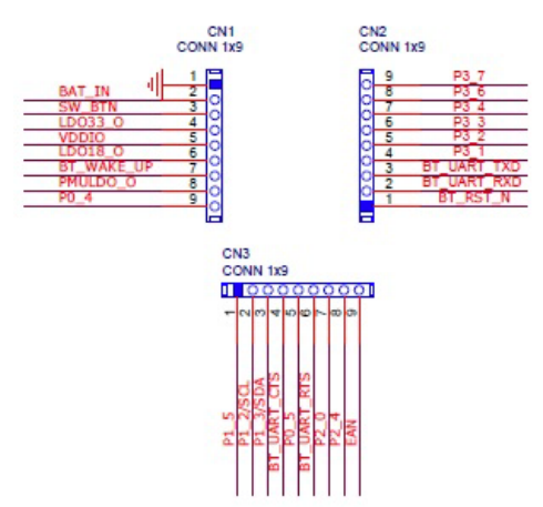
There are other development boards where this one can be connected to via one if its connectors, but for simple BM78 development this one can be operated by its own.
Conclusion
It took me quite some time to figure out how to properly use this module working properly. Especially configuring the module from a PIC directly was a quite a pickle. See my MCLIB for the implementation of that. I will write another post detailing the communication between the BM78 module and a microcontroller.