Even though some microcontrollers have a lot of GPIOs, sometimes one may find himself/herself in the need of even more. The MCP23017 is made for that purpose.
In the previous post we learned how to setup a project to program PIC16F18855/75. We will use the same PIC in this for this tutorial since it has the needed I2C bus. For setting up the project and configuring the MSSP as an I2C Master please refer to the previous post. We also will use the LCD from there.
MCP23017
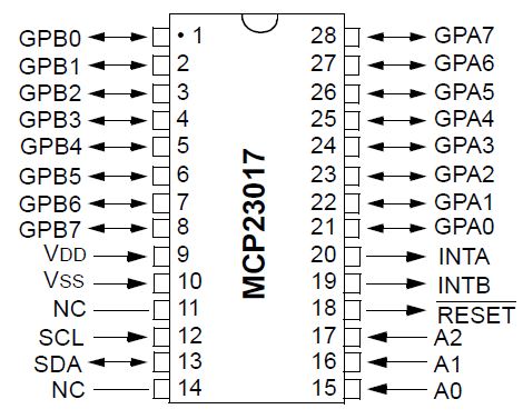
The MCP23017 comes with 16 GPIOs and can be configured to communicate over I2C bus within the address space 0x20 – 0x27. The address can be configured using the A0-A1 pins from 0 (0x20) to 7 (0x27). The 16 GPIOs are divided into 2 ports (A,B) each with 8 pins (8bit). See the datasheet below for more information about how to use this chip.
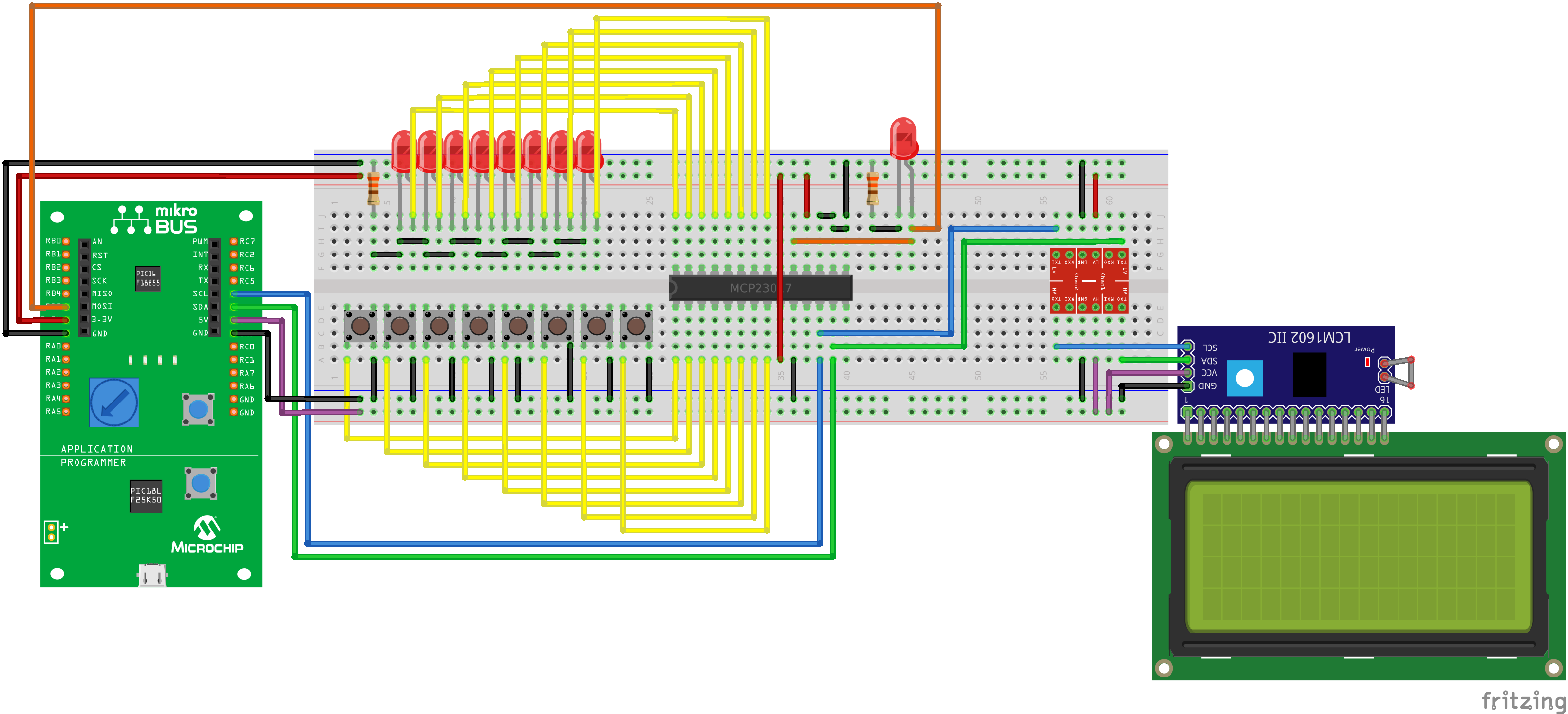
The Wiring
We are going to setup an example, where the whole port A is configured as an output and port B as an input. We’ve connected 8 LEDs with a 330Ohm resistor in series to limit the current to port A and 8 buttons pulling the outputs of port B down. There are configurable internal pull-up resistors inside the MCP23017 chip which can be used if a pin is configured as input.
We are also using the INTB pin to detect changes and notify the PIC with an interrupt. Interrupts are enabling a kind of concurrency here.
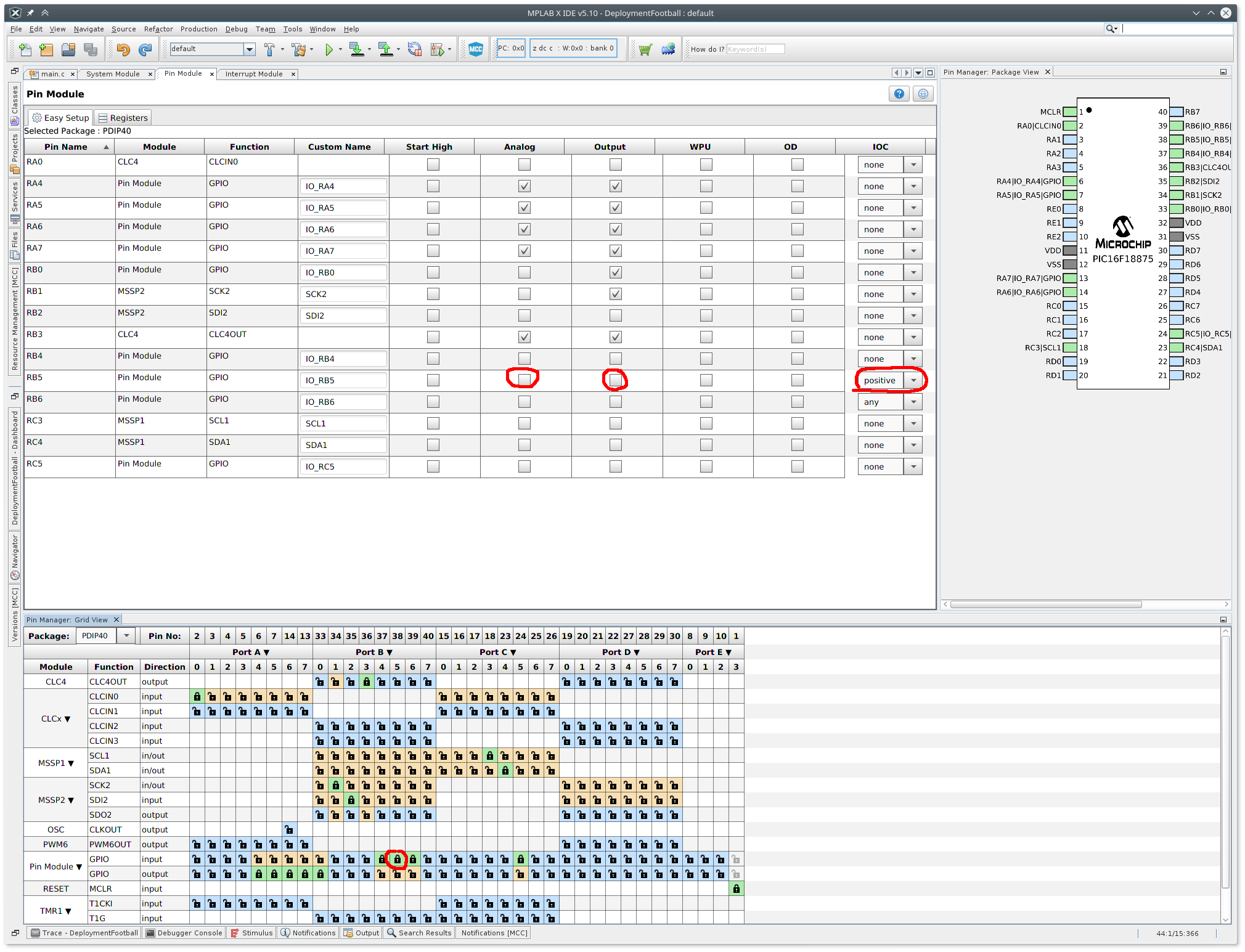
Interrupts setup
Using the MPLAB’s Code Configurator (MCC) we set the RB5 in the “Pin Manager” tab as GPIO input. We also make sure that in the “Pin Module” tab the RB5‘s Analog checkbox and the Output checkbox are unchecked and that “positive” is selected in the Interrupt-on-change (IOC) combo. Dont forget to click “Generate” button in the “Resource Management [MCC]“. This will trigger an interrupt when with the rising edge of the RB5 pin.
The Code
We will reuse the i2c module (modules/i2c.h and modules/i2c.c) and the lcd module (modules/lcd.h and modules/lcd.c) from our last post and add a new mcp23017 module (modules/mcp23017.h). We only need a header file since the I2C communication is very simple.
/*
 * File:   mcp23017.h
 * Author: Jan Kubovy <jan@kubovy.eu>
 */

#ifndef MCP23017_H
#define	MCP23017_H

#ifdef	__cplusplus
extern "C" {
#endif

// PIN registers for direction
// IO<7:0> <R/W-1> (default: 0b11111111)
//   1 = Pin is configured as an input
//   0 = Pin is configured as an output
#define MCP_IODIRA 0x00   // GPA
#define MCP_IODIRB 0x01   // GPB

// Input polarity registers
// IP<7:0> <R/W-0> (default: 0b00000000)
//   1 = GPIO register bit reflects the opposite logic state of the input pin
//   0 = GPIO register bit reflects the same logic state of the input pin
#define MCP_IPOLA 0x02    // GPA
#define MCP_IPOLB 0x03    // GPB

// Interrupt-on-change control registers
// GPINT<7:0> <R/W-0> (default: 0b00000000)
//   1 = Enables GPIO input pin for interrupt-on-change event
//   0 = Disables GPIO input pin for interrupt-on-change event
#define MCP_GPINTENA 0x04 // GPA
#define MCP_GPINTENB 0x05 // GPB

// Default compare registers for interrupt-on-change
// DEF<7:0> <R/W-0> (default: 0b00000000)
#define MCP_DEFVALA 0x06  // GPA
#define MCP_DEFVALB 0x07  // GPB

// Interrupt control register
// IOC<7:0> <R/W-0> (default: 0b00000000)
//   1 = Pin value is compared against the associated bit in the DEFVAL register.
//   0 = Pin value is compared against the previous pin value.
#define MCP_INTCONA 0x08  // GPA
#define MCP_INTCONB 0x09  // GPB

// I/O expander configuration register
// bit7<R/W-0> BANK: Controls how the registers are addressed
//     1 = The registers associated with each port are separated into different
//         banks
//     0 = The registers are in the same bank (addresses are sequential)
// bit6<R/W-0> MIRROR: INT Pins Mirror bit
//     1 = The INT pins are internally connected
//     0 = The INT pins are not connected. INTA is associated with  PORTA and
//         INTB is associated with PORTB
// bit5<R/W-0> SEQOP: Sequential Operation mode bit
//     1 = Sequential operation disabled, address pointer does not  increment
//     0 = Sequential operation enabled, address pointer increments
// bit4<R/W-0> DISSLW: Slew Rate control bit for SDA output
//     1 = Slew rate disabled
//     0 = Slew rate enabled
// bit3<R/W-0> HAEN: Hardware Address Enable bit (MCP23S17 only) (Note 1)
//     1 = Enables the MCP23S17 address pins.
//     0 = Disables the MCP23S17 address pins.
// bit2<R/W-0> ODR: Configures the INT pin as an open-drain output
//     1 = Open-drain output (overrides the INTPOL bit.)
//     0 = Active driver output (INTPOL bit sets the polarity.)
// bit1<R/W-0> INTPOL: This bit sets the polarity of the INT output pin
//     1 = Active-high
//     0 = Active-low
// bit0<U-0> Unimplemented: Read as '0'
#define MCP_IOCON 0x0A    //
#define MCP_IOCON2 0x0B   //

// Pull-up resistor configuration registers
// PU<7:0> <R/W-0> (default: 0b00000000)
//   1 = Pull-up enabled
//   0 = Pull-up disabled
#define MCP_GPPUA 0x0C    // GPA
#define MCP_GPPUB 0x0D    // GPB

// Interrupt flag registers
// INT<7:0> <R-0> (default: 0b00000000)
//   1 = Pin caused interrupt.
//   0 = Interrupt not pending
#define MCP_INTFA 0x0E    // GPA
#define MCP_INTFB 0x0F    // GPB

// Interrupt captured registers
// ICP<7:0> <R-x>
//   1 = Logic-high
//   0 = Logic-low
#define MCP_INTCAPA 0x10  // GPA
#define MCP_INTCAPB 0x11  // GPB

// Port registers
// GP<7:0> <R/W-0> (default: 0b00000000)
//   1 = Logic-high
//   0 = Logic-low
#define MCP_GPIOA 0x12    // GPA
#define MCP_GPIOB 0x13    // GPB

// Output latch registers
// OL<7:0> <R/W-0> (default: 0b00000000)
//   1 = Logic-high
//   0 = Logic-low
#define MCP_OLATA 0x14    // GPA
#define MCP_OLATB 0x15    // GPB

#ifdef	__cplusplus
}
#endif

#endif	/* MCP23017_H */
Now in our main.c we can talk to the MCP23017. We do not process anything big inside the interrupt, just set a flag and do the actual work in the main loop:
#define MCP23017_1_ADDRESS = 0x20 // Change this according to ur setup
#define LCD_ADDRESS 0x27 // Change this according to ur setup

#define LCD_COLS 20
#define LCD_ROWS 4

#include <stdio.h>
#include "mcc_generated_files/mcc.h"
#include "modules/i2c.h"
#include "modules/lcd.h"
#include "modules/mcp23017.h"

bool doRB5Interrupt = false;

void showMCP23017Configuration(void) {
    uint8_t gpio;

    LCD_clear();
    LCD_backlight(true);

    gpio = I2C_receive(0x20, MCP_INTCAPB) | I2C_receive(0x20, MCP_GPIOB);

    LCD_send_string("MCP23017", 1);
    LCD_send_string("--------------------", 2);

    char message[LCD_COLS + 1] = "GPIOB: ";
    for (uint8_t i = 0; i < 8; i++) {
        message[i + 7] = (gpio & 0b10000000) ? '1' : '0';
        gpio <<= 1;
    }
    message[7 + 8] = '\0';
    LCD_send_string(message, 4);

    I2C_sendN(0x20, 2, MCP_IODIRA, 0x00);
    I2C_sendN(0x20, 2, MCP_OLATA, 0x00);
    I2C_sendN(0x20, 2, MCP_OLATA, 0b10101010);

    message[4] = 'A';
    gpio = I2C_receive(0x20, MCP_GPIOA);
    for (uint8_t i = 0; i < 8; i++) {
        message[i + 7] = (gpio & 0b10000000) ? '1' : '0';
        gpio <<= 1;
    }
    message[7 + 8] = '\0';
    LCD_send_string(message, 3);

    __delay_ms(250);

    I2C_sendN(0x20, 2, MCP_OLATA, 0b01010101);
    LATA |= 0b00100000;

    gpio = I2C_receive(0x20, MCP_GPIOA);
    for (uint8_t i = 0; i < 8; i++) {
        message[i + 7] = (gpio & 0b10000000) ? '1' : '0';
        gpio <<= 1;
    }
    message[7 + 8] = '\0';
    LCD_send_string(message, 3);
}

void pinRB5InterruptHandler(void) {
    doRB5Interrupt = true;
}

void main(void) {
    SYSTEM_Initialize(); // initialize the device

    // When using interrupts, you need to set the Global and Peripheral
    // Interrupt Enable bits Use the following macros to:
    INTERRUPT_GlobalInterruptEnable();      // Enable the Global Interrupts
    //INTERRUPT_GlobalInterruptDisable();   // Disable the Global Interrupts
    INTERRUPT_PeripheralInterruptEnable();// Enable the Peripheral Interrupts
    //INTERRUPT_PeripheralInterruptDisable(); // Disable the Peripheral Interrupts

    IOCBF5_SetInterruptHandler(pinRB5InterruptHandler);

    I2C_sendN(0x20, 2, MCP_IOCON, 0b00000010); // sets the polarity of the INT output pin to active-high

    I2C_sendN(0x20, 2, MCP_IODIRA, 0b00000000); // GPIOA output

    I2C_sendN(0x20, 2, MCP_IODIRB, 0b11111111); // GPIOB input (default)
    I2C_sendN(0x20, 2, MCP_IPOLB, 0b11111111); // Reverse polarity on GPIOB
    I2C_sendN(0x20, 2, MCP_GPPUB, 0b11111111); // Enable pull-up on GPIOB
    I2C_sendN(0x20, 2, MCP_GPINTENB, 0b11111111); // Enable interrupt on GPIOB
    I2C_sendN(0x20, 2, MCP_INTCONB, 0b00000000); // Interrupt-on-change (default)
    I2C_receive(0x20, MCP_INTCAPB); // Read to clear interrupt

    __delay_ms(500);

    LCD_init(LCD_ADDRESS, LCD_COLS, LCD_ROWS);
    LCD_backlight(true);

    while (1) {
        if (doRB5Interrupt) {
            doRB5Interrupt = false;
            // Interrupt-on-change flag and RB5 pin flag status check
            LCD_clear();
            LCD_send_string("|c|Interrupt caught!", 2);
            __delay_ms(250);
            showMCP23017Configuration();
        }
    }
}
Conclusion
Since the MCP23017 address space is 3bits, we can add up to 8 such chips on one I2C bus and expanding this way our circuit with up to 8 * 16 = 128 GPIOs. Some PICs, including this one have more than one I2C module enabling even bigger extension. That should be enough for while.
Happy PICing.