We’ve already done some projects with Rasperry Pi. While Adruino and Raspberry Pi are great prototyping tools allowing fast development of proof of concepts, lot of resources, libraries and examples, it also comes with some pitfalls.
In case of Raspberry Pi it is a full-blown computer with all common peripherals, operating system, etc. This means, e.g., the need to boot for a couple of minutes. Both Adruino and Raspberry come with a ready-made PCB where all those peripherals reside and consume power. If one wants to make a step forward and convert his/her prototypes into real product an embedded system comes in mind. This may have a couple advantages: custom PCB fitting a certain casing, only used peripherals, much lower power consumption enabling long-term battery powered systems, etc.
When developing an embedded system one may have the need to have some output, e.g. monitor. This is why we’ve chosen to make the first example with an LCD. The presented application may be also reused in other project during development even if the final system will not have any LCD.
For the development the PIC16F18855/75 was chosen since it has most of the peripherals used in our previous projects. But it should be possible to adapt to any PIC microcontroller with required peripherals. Those are 8bit mid-range microcontrollers.

We also use the MPLAB X IDE v5.10 to write the code for our microcontroller. To configure the MSSP module we recommend to use MPLAB’s Code Configurator (v3 as of the time of writing this post). Also we use the XC8 Compiler v2.05.
The circuit
The wiring is pretty straight forward since the PIC contains an I2C interface in form of a MSSP module.
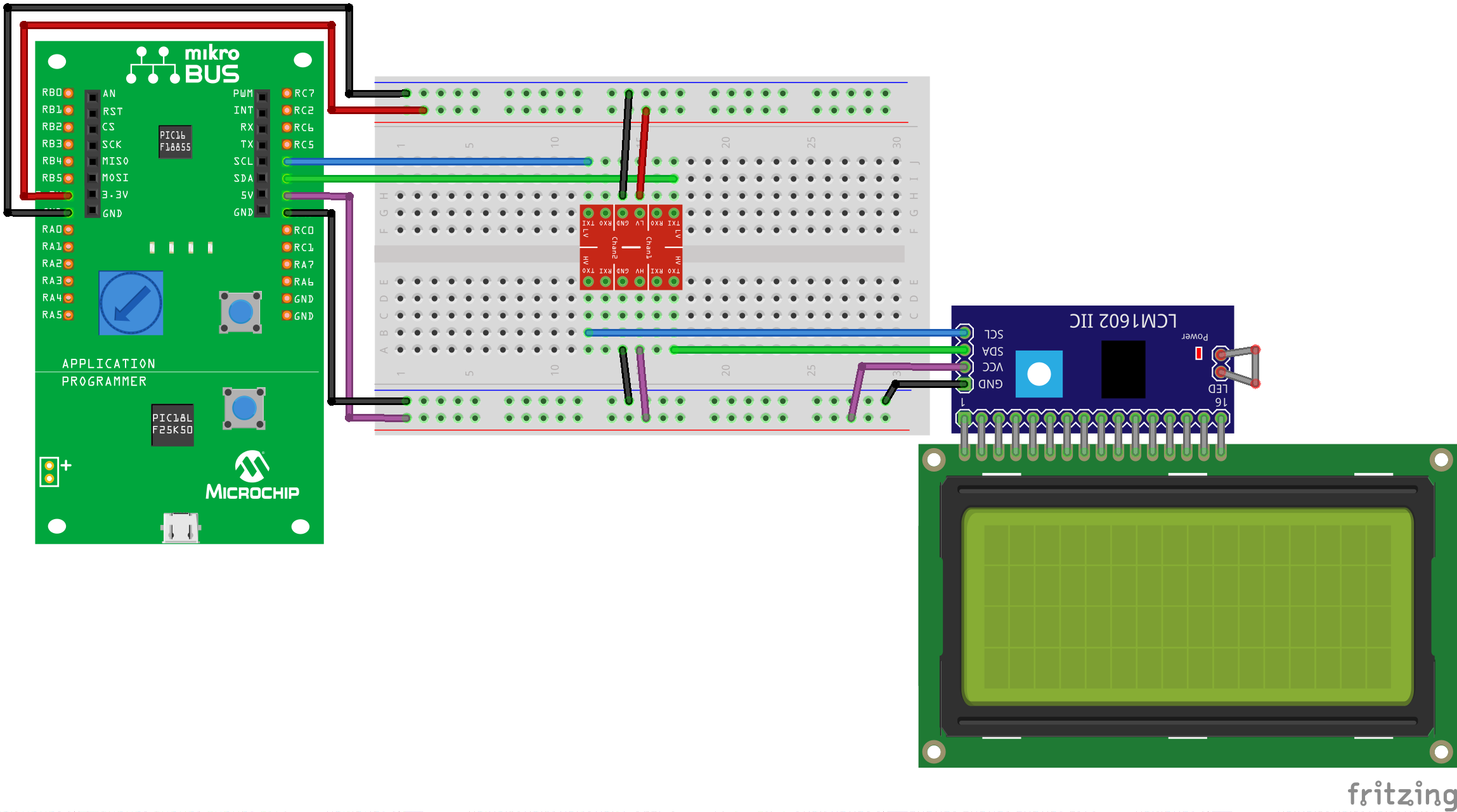

We are going to operate our PIC in 3V3 mode. Our LCD module requires 5V logic and therefore we need a logic level converter from 3V3 to 5V logic. This means that our logical “1” will be ~3,3V for the PIC and ~5V for the LCD. Logical “0” will be in both cases 0V (GND).
We feed the development board with 5V from the USB and the board provides PINs for both required voltages (3,3V and 5V). We connect both voltages to our Breadboard and connect them to the proper pins of our logic level converter. We use the 2 TXI pins of the logic level converter, one for SDA (signal) and the second for SCK (clock) of the I2C of our PIC. The 2 TXO pins will then connect to the LCM1602 IIC module’s SDA and SCK pins. We power the LCD module with 5V.
Now that we have the wiring done let’s go to do some code…
Setting up the project
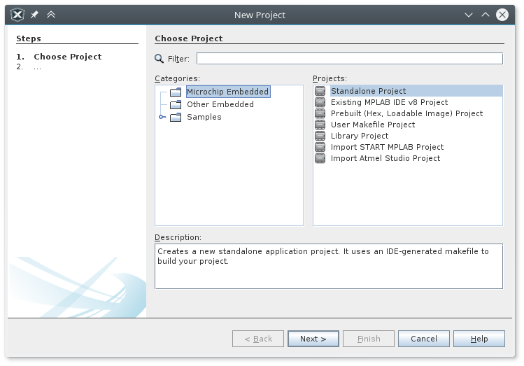
We open the MPLAB X IDE and create a new project: File -> New Project. Select “Microchip Embedded” category, “Standalone Project” and click Next.
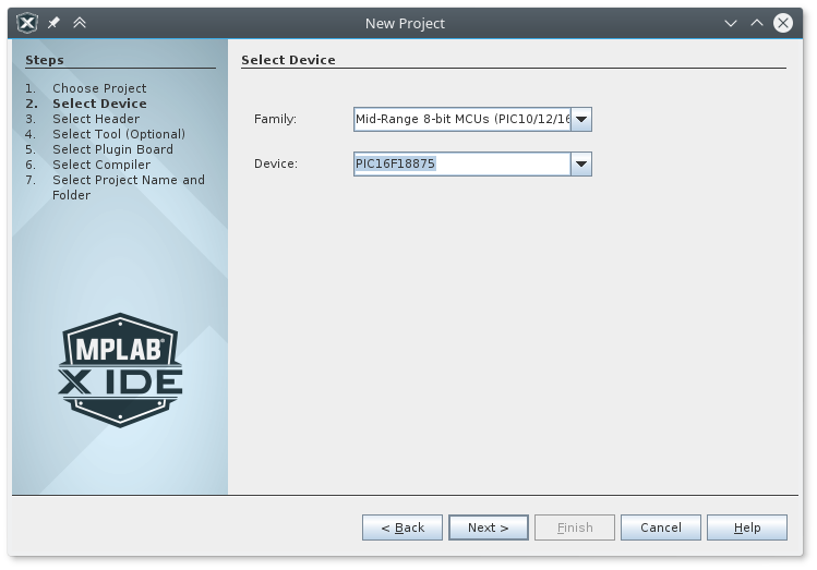
Next we select the microcontroller’s family and the concrete device. In our case it is the “PIC16F18875” and click Next.
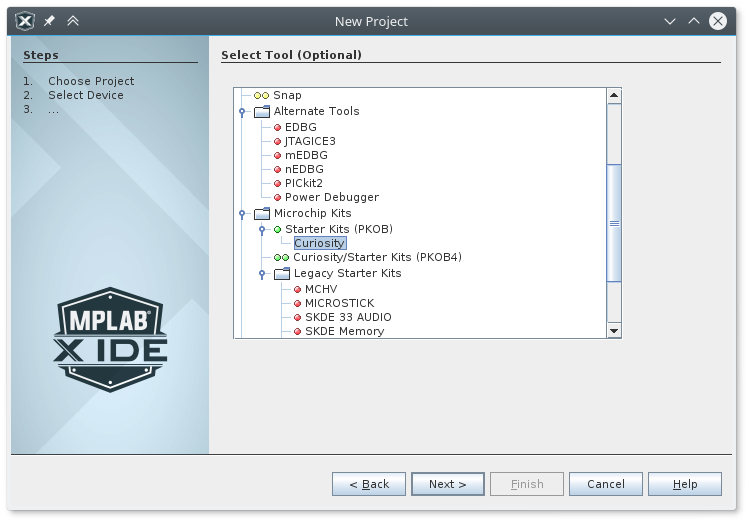
Optionally we need to select the programmer. In our case it will be the “Curiosity Starter Kit (PKOB)” and click Next.
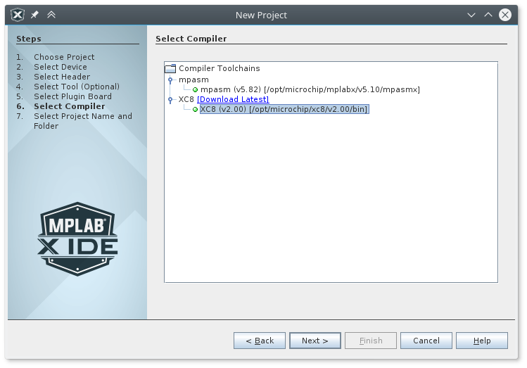
Next, we need to select a compiler to be used. By default the IDE comes with a mpasm compiler preinstalled. The XC8 compiler needs to be downloaded and installed separately (see above). There is also a payed version of the XC8 compiler which does some more optimization. We are going to use the free version in this example.
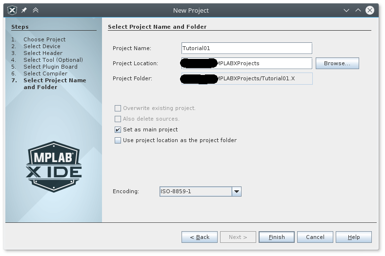
Last, the project name and location needs to be filled. Also select “Set as main project” if not already checked and click Finish.
Configuring the Microcontroller and its peripherals
The new project gets created and if we have MPLAB’s Code Configurator (MCC) also installed it will get open. If not we can open it with the “MCC” icon in the toolbar on the top. You may also want to select the proper PIC package in the “Pin Manager” tab so the microcontroller’s illustration is corresponding to your actual chip. We make sure that the selected oscillator is the Internal High-Frequency Oscillator (HFINTOSC). We set the HF Internal Clock to 8Mhz and the Clock Divider to 1.

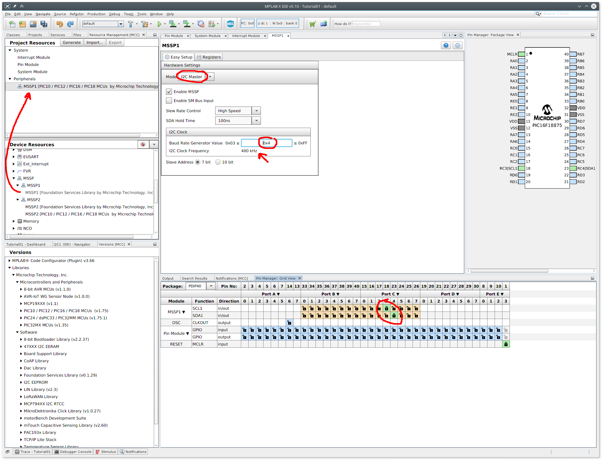
Next, we add our only peripheral, the MSSP peripheral. This can be done in the “Resource Management [MCC]” tab. By double-clicking a peripheral in the “Device Resources” part will move that peripheral to “Project Resources“. The Master Synchronous Serial Port (MSSP) combines an I2C and SPI in one peripheral. We want our MSSP to be an I2C in master mode – select Mode: “I2C Master“. We also want our I2C protocol to work with the speed of 400kHz and therefore we need to put the value “0x04” into the SSP1ADD register (see datasheet). We can also see in the Pin Manager tab that by default our SCL1 (a.k.a. SCK) will be wired to RC3 (pin 18) and our SDA1 will be wired to RC4 (pin 23). If we want we can change that here.
(Please note that this may not correspond with our wiring drawing above)
Now we are done with the basic setup. The last thing to do is to click the “Generate” button in the “Resource Management [MCC]” tab.
The MCC is a great tool to create scaffolding and setup of our microcontroller, especially if you just started programming microcontroller. All we did via this plugin can also be done in code setting the relevant registers with the help of the datasheet of the concrete microcontroller. This may be indeed overwhelming in the beginning. Look at the generated code may give one a good idea what needs to be manually done if one chooses to go hard-core.
The MCC generates all needed header and source files to the “MCC Generated Files” folder. They may be changed but take care when changing something with the MCC plugin and regenerating not to loose your changes. Most of the time changes in the generated files may be avoided. Some time ago the MCC also shows a merging tool in case some manual changes may be overwritten by the generator in a similar way as version control system would do.
Source Code
The important file one wants to implement his/her code is the main.c source. We want to keep things nice and clean so we create a “modules” folder. There we create 4 files: i2c.h, i2c.c, lcd.h and lcd.c. Let’s begin with the I2C module.
I2C Module
The modules/i2c.h header file contains some configurations, constants and function prototypes. As a convention we use the “I2C_” prefix in this module.
/*
 * File:   i2c.h
 * Author: Jan Kubovy <jan@kubovy.eu>
 */

#ifndef I2C_H
#define	I2C_H

#ifdef	__cplusplus
extern "C" {
#endif

#include <stdbool.h>
#include <stdint.h>
#include <stdarg.h>

// Configuration which SPP module to use.
#ifndef I2C_SSPSTAT
#define I2C_SSPSTAT SSP1STAT
#define I2C_SSPCON2 SSP1CON2
#define I2C_BUFFER SSP1BUF
#endif

// Operation modes
#define I2C_MODE_WRITE 0x00
#define I2C_MODE_READ 0x01

// Acknowledgments
#define I2C_ACK 0x01
#define I2C_NACK 0x00

/**
 *  Initiates the START condition on SDA and SCL pins.
 */
void I2C_start(void);

/**
 *  Initiates the REPEATED START condition on SDA and SCL pins.
 */
void I2C_repeated_start(void);

/**
 *  Initiate the STOP condition on SDA and SCL pins
 */
void I2C_stop(void);

/**
 * Select a device by its address and the communication mode.
 *
 * The address will be shifted about 1 bit to the right and the mode bit will
 * be inserted on the last position. Therefore only first 7 bits of the 8 bit
 * address will be effectively used.
 *
 * @param address 7bit address, the 8th bit is ignored.
 * @param mode One of: <code>I2C_MODE_WRITE</code>, <code>I2C_MODE_READ</code>.
 */
void I2C_select(uint8_t address, bool mode);

/**
 * Writes 8 bits to the I2C bus.
 *
 * Following the communication start (e.g. <code>I2C_start</code>) and device
 * selection (<code>I2C_select</code>) this function can be used to writes
 * 8 bits to the I2C bus.
 *
 * @param data Data to be written.
 */
void I2C_write(uint8_t data);

/**
 * Reads 8 bits from the I2C bus.
 *
 * Following the communication start (e.g. <code>I2C_start</code>) and device
 * selection (<code>I2C_select</code>) this function can be used to read
 * 8 bits from the I2C bus.
 *
 * @param ack <code>I2C_ACK</code>, <code>I2C_NACK</code>.
 * @return 8bits read from the I2C bus.
 */
uint8_t I2C_read(uint8_t ack);

/**
 * Send 8bits to defined address.
 *
 *  This is a shorthand to start communication with <code>address</code> in
 *  <code>I2C_MODE_WRITE</code> mode and send <code>data</code>.
 *
 * @param address 7bit address, the 8th bit is ignored.
 * @param data Data to be written.
 */
void I2C_send(uint8_t address, uint8_t data);

/**
 *  Send N times 8bits to defined address.
 *
 *  This is a shorthand to start communication with <code>address</code> in
 *  <code>I2C_MODE_WRITE</code> mode and send <code>data</code>.
 *
 * @param address 7bit address, the 8th bit is ignored.
 * @param n Number of bytes to be send (number of vararg parameters)
 * @param ... Data to be written (n times <code>uint8_t</code>).
 */
void I2C_sendN(uint8_t address, uint8_t n, ...);

/**
 *  Receives 8bits from defined address.
 *
 *  This is a shorthand to start communication with <code>address</code> in
 *  <code>I2C_MODE_WRITE</code> mode and write <code>reg</code> to tell the
 *  other device what data it should send back then switching to
 *  <code>I2C_MODE_READ</code> and read the response.
 *
 * @param address 7bit address, the 8th bit is ignored.
 * @param reg Information for the other device what data should be send back.
 * @return 8bits response.
 */
uint8_t I2C_receive(uint8_t address, uint8_t reg);

#ifdef	__cplusplus
}
#endif

#endif	/* I2C_H */
The implementation of the start, stop, device select, read and write operations functionality is then present in the modules/i2c.c file.
/*
 * File:   i2c.c
 * Author: Jan Kubovy <jan@kubovy.eu>
 */

#include <stdbool.h>
#include <stdint.h>
#include <stdarg.h>
#include "../mcc_generated_files/mcc.h"
#include "i2c.h"

inline void I2C_wait(void) {
    // wait for start bit to clear in SSPSTAT and bits 0 to 4 in SSPCON2
    while ((I2C_SSPSTAT & 0x04) || (I2C_SSPCON2 & 0x1F));
}

void I2C_start(void) {
    I2C_wait();
    I2C_SSPCON2 |= 0x01; // SEN=1 -> initiate the START condition on SDA and SCL pins
}

void I2C_repeated_start(void) {
    I2C_wait();
    I2C_SSPCON2 |= 0x02; // RSEN=1  -> initiate REPEATED START condition on SDA and SCL pins
}

void I2C_stop(void) {
    I2C_wait();
    I2C_SSPCON2 |= 0x04; // PEN=1 -> initiate the STOP condition on SDA and SCL pins
}

void I2C_select(uint8_t address, bool mode) {
    I2C_write(address << 1 | mode);
}

uint8_t I2C_read(uint8_t ack) {
    uint8_t temp;
    I2C_wait();
    RCEN1 = 1;      // enable receive mode for I2c
    I2C_wait();
    temp = SSP1BUF; // load data from Buffer to the temp
    I2C_wait();
    ACKDT1 = (ack); // 0-- not ACK , 1-- ACK
    ACKEN1 = 1;     // Send Acknowledgement
    return temp;
}

void I2C_write(uint8_t data) {
    I2C_wait();
    SSP1BUF = data;  // load data into SSPBUF register
}

void I2C_send(uint8_t address, uint8_t data) {
    I2C_start();
    I2C_select(address, I2C_MODE_WRITE);
    I2C_write(data);
    I2C_stop();
}

void I2C_sendN(uint8_t address, uint8_t n, ...) {
    uint8_t i;
    va_list argp;
    va_start(argp, n);
    I2C_start();
    I2C_select(address, I2C_MODE_WRITE);
    for (i=0; i < n; i++) {
        I2C_write(va_arg(argp, uint8_t));
    }
    I2C_stop();
    va_end(argp);
}

uint8_t I2C_receive(uint8_t address, uint8_t reg) {
    I2C_send(address, reg);

    I2C_start();
    I2C_select(address, I2C_MODE_READ);
    uint8_t data = I2C_read(I2C_ACK);
    I2C_stop();
    return data;
}
LCD Module
The LCD module then uses our I2C module and adds some LCD specific functionality. The header file contains some LCD specific constants
/*
 * File:   lcd.h
 * Author: Jan Kubovy <jan@kubovy.eu>
 */

#ifndef LCD_H
#define	LCD_H

#ifdef	__cplusplus
extern "C" {
#endif

#include <stdbool.h>
#include <stdint.h>

// Commands
#define LCD_CLEARDISPLAY 0x01        // 0b00000001
#define LCD_RETURNHOME 0x02          // 0b00000010
#define LCD_ENTRYMODESET 0x04        // 0b00000100
#define LCD_DISPLAYCONTROL 0x08      // 0b00001000
#define LCD_CURSORSHIFT 0x10         // 0b00010000
#define LCD_FUNCTIONSET 0x20         // 0b00100000
#define LCD_SETCGRAMADDR 0x40        // 0b01000000
#define LCD_SETDDRAMADDR 0x80        // 0b10000000

// Flags for display entry mode
#define LCD_ENTRYRIGHT 0x00
#define LCD_ENTRYLEFT 0x02           // 0b00000010
#define LCD_ENTRYSHIFTINCREMENT 0x01
#define LCD_ENTRYSHIFTDECREMENT 0x00

// Flags for display on/off control
#define LCD_DISPLAYON 0x04           // 0b00000100
#define LCD_DISPLAYOFF 0x00          // 0b00000000
#define LCD_CURSORON 0x02            // 0b00000010
#define LCD_CURSOROFF 0x00           // 0b00000000
#define LCD_BLINKON 0x01             // 0b00000001
#define LCD_BLINKOFF 0x00            // 0b00000000

// Flags for display/cursor shift
#define LCD_DISPLAYMOVE 0x08         // 0b00001000
#define LCD_CURSORMOVE 0x00          // 0b00000000
#define LCD_MOVERIGHT 0x04           // 0b00000100
#define LCD_MOVELEFT 0x00            // 0b00000000

// Flags for function set
#define LCD_8BITMODE 0x10            // 0b00010000
#define LCD_4BITMODE 0x00            // 0b00000000
#define LCD_2LINE 0x08               // 0b00001000
#define LCD_1LINE 0x00               // 0b00000000
#define LCD_5x10DOTS 0x04            // 0b00000100
#define LCD_5x8DOTS 0x00             // 0b00000000

// Flags for backlight
#define LCD_BACKLIGHT 0x08           // 0b00001000
#define LCD_NOBACKLIGHT 0x00         // 0b00000000

// Lines
#define LCD_LINE1 0x80               // 0b10000000
#define LCD_LINE2 0xC0               // 0b11000000
#define LCD_LINE3 0x94               // 0b10010100
#define LCD_LINE4 0xD4               // 0b11010100

#define En 0b00000100                // Enable bit
#define Rw 0b00000010                // Read/Write bit
#define Rs 0b00000001                // Register select bit

/**
 * LCD module intialization.
 *
 * @param address I2C 7bit address of the LCD.
 * @param cols Number of columns.
 * @param rows Number of rows.
 */
void LCD_init(uint8_t address, uint8_t cols, uint8_t rows);

/**
 * Clear the content of the LCD.
 */
void LCD_clear(void);

/**
 * Turn LCD's backlight on or off.
 *
 * @param on Whether to turn the backlight on or off.
 */
void LCD_backlight(bool on);

/**
 * Send a command to the LCD.
 *
 * @param command The command.
 */
void LCD_send_cmd(uint8_t command);

/**
 * Send data to the LCD.
 *
 * @param data The data.
 */
void LCD_send_data(uint8_t data);

/**
 * Send string to the LCD.
 *
 * The string length will be trimmed to the number of the LCD's columns. Also
 * multiple lines may be send at once by separating the line with a new line
 * (\n). All lines bigger than the number of the LCD's rows will be ignore.
 *
 * There are some modifiers which can be added on the beginning of each line:
 * <li><code>|c|</code>: will center the text</li>
 * <li><code>|l|</code>: will left-align the text (the default)</li>
 * <li><code>|r|</code>: will right-align the text</li>
 * <li><code>|d|MS|</code>: type animation with <code>MS</code> millisecond delay between each character</li>
 *
 * @param str String to be sent.
 * @param line Line the string should be display on or begin at in case of multi-line string.
 */
void LCD_send_string(char *str, uint8_t line);

#ifdef	__cplusplus
}
#endif

#endif	/* LCD_H */
The modules/lcd.c then implement those function:
/*
 * File:   lcd.c
 * Author: Jan Kubovy <jan@kubovy.eu>
 */

#include "../mcc_generated_files/mcc.h"
#include "i2c.h"
#include "lcd.h"

uint8_t _LCD_address;
uint8_t _LCD_cols;
uint8_t _LCD_rows;
uint8_t _LCD_backlight = LCD_BACKLIGHT;

void LCD_init(uint8_t address, uint8_t cols, uint8_t rows) {
    _LCD_address = address;
    _LCD_cols = cols;
    _LCD_rows = rows;

    LCD_send_cmd(LCD_RETURNHOME | LCD_CLEARDISPLAY);
    LCD_send_cmd(LCD_RETURNHOME | LCD_CLEARDISPLAY);
    LCD_send_cmd(LCD_RETURNHOME | LCD_CLEARDISPLAY);
    LCD_send_cmd(LCD_RETURNHOME);

    //           0b00100000        0b00001000  0b00000000    0b00000000 = 0b00101000 (0x28)
    LCD_send_cmd(LCD_FUNCTIONSET | LCD_2LINE | LCD_5x8DOTS | LCD_4BITMODE);
    //           0b00001000           0b00000100 = 0b00001100 = (0x0C)
    LCD_send_cmd(LCD_DISPLAYCONTROL | LCD_DISPLAYON | LCD_CURSOROFF | LCD_BLINKOFF);
    //           0b00000001 (0x01)
    LCD_send_cmd(LCD_CLEARDISPLAY);
    //           0b00000100         0b00000010 = 0b00000110 (0x06)
    LCD_send_cmd(LCD_ENTRYMODESET | LCD_ENTRYLEFT);

    __delay_ms(200);

    LCD_send_cmd(LCD_CLEARDISPLAY);
    LCD_send_cmd(LCD_RETURNHOME);
    LCD_backlight(false);
}

void LCD_clear(void) {
    LCD_send_cmd(LCD_CLEARDISPLAY);
    LCD_send_cmd(LCD_RETURNHOME);
    __delay_ms(200);
}

void LCD_backlight(bool on) {
    _LCD_backlight = on ? LCD_BACKLIGHT : LCD_NOBACKLIGHT;
    I2C_start();
    I2C_select(_LCD_address, I2C_MODE_WRITE);
    I2C_write(_LCD_backlight);
    I2C_stop();
}

void LCD_send_cmd(unsigned char command) {
    unsigned char nibble_lower, nibble_upper;
    nibble_lower = (command<<4) & 0xF0; //select lower nibble by moving it to the upper nibble position
    nibble_upper = command & 0xF0;      //select upper nibble

    I2C_start();
    I2C_select(_LCD_address, I2C_MODE_WRITE);

    I2C_write(nibble_upper | _LCD_backlight | En); // enable=1 and rs =0
    I2C_write(nibble_upper | _LCD_backlight);      // enable=0 and rs =0

    I2C_write(nibble_lower | _LCD_backlight | En); // enable =1 and rs =0
    I2C_write(nibble_lower | _LCD_backlight);      // enable=0 and rs =0

     I2C_stop();
}

void LCD_send_data(unsigned char data) {
    unsigned char nibble_lower, nibble_upper;
    nibble_lower = (data<<4) & 0xF0;  //select lower nibble by moving it to the upper nibble position
    nibble_upper = data & 0xF0;  //select upper nibble

    I2C_start();
    I2C_select(_LCD_address, I2C_MODE_WRITE);

    I2C_write(nibble_upper | _LCD_backlight | En | Rs); // enable=1 and rs =1 // 1101
    I2C_write(nibble_upper | _LCD_backlight | Rs);      // enable=0 and rs =1

    I2C_write(nibble_lower | _LCD_backlight | En | Rs); // enable=1 and rs =1
    I2C_write(nibble_lower | _LCD_backlight | Rs);      // enable=0 and rs =1

    I2C_stop();
}

inline void LCD_select_line(uint8_t line) {
    switch(line) {
        case 2:
            LCD_send_cmd(LCD_LINE2);
            break;
        case 3:
            LCD_send_cmd(LCD_LINE3);
            break;
        case 4:
            LCD_send_cmd(LCD_LINE4);
            break;
        default:
            LCD_send_cmd(LCD_LINE1);
            break;
    }
}

void LCD_send_string(char *str, uint8_t line) {
    while (*str && line > 0 && line <= _LCD_rows) {
        LCD_select_line(line++);
        uint8_t col=0, prefix=0;
        uint16_t i, delay = -1;

        if (*str == '|' && *(str + 2) == '|') {
            if (*(str + 1) == 'c' || *(str + 1) == 'r') {
                while(*(str + prefix + 3) && *(str + prefix + 3) != '\n') prefix++;
                if (prefix > _LCD_cols) prefix = _LCD_cols;
                prefix = _LCD_cols - prefix;
                if (*(str + 1) == 'c') prefix /= 2;
            }
            if (*(str + 1) == 'd') {
                i = 0;
                delay = 0;
                while(*(str + i + 3) >= '0' && *(str + i + 3) <= '9') {
                    delay = delay * 10 + (*(str + (i++) + 3) - 48);
                }
                str += i + 1;
            }
            str += 3;
        }

        for (i=0; i < prefix; i++) LCD_send_data(' ');
        while (*str && *str != '\n' && col++ < _LCD_cols) {
            LCD_send_data(*str++);
            if (delay == -1) __delay_us(500);
            else for(i = 0; i < delay; i++) __delay_ms(1);
        }
        if (col >= _LCD_cols) while (*str && *str != '\n') *str++;
        if (*str == '\n') *str++;
    }
}
Wrapping it up
Now let’s test if everything is working. The main.c may contain something like this:
#define LCD_ADDRESS 0x27 // change this according to ur setup

#define LCD_COLS 20
#define LCD_ROWS 4

#include "mcc_generated_files/mcc.h"
#include "modules/i2c.h"
#include "modules/lcd.h"

void main(void)
{
    // initialize the device
    SYSTEM_Initialize();

    // When using interrupts, you need to set the Global and Peripheral Interrupt Enable bits
    // Use the following macros to:

    // Enable the Global Interrupts
    //INTERRUPT_GlobalInterruptEnable();

    // Enable the Peripheral Interrupts
    //INTERRUPT_PeripheralInterruptEnable();

    // Disable the Global Interrupts
    //INTERRUPT_GlobalInterruptDisable();

    // Disable the Peripheral Interrupts
    //INTERRUPT_PeripheralInterruptDisable();

    __delay_ms(1000);

    LCD_init(LCD_ADDRESS, LCD_COLS, LCD_ROWS);
    LCD_backlight(true);
    LCD_send_string("|d|100|....................\0", 1);
    LCD_send_string("|c|hello world\0", 3);

    __delay_ms(1000);

    LCD_backlight(false);

    __delay_ms(500);

    LCD_send_string("|r|backlight off\0", 4);

    __delay_ms(500);

    LCD_backlight(true);
    LCD_send_string("|r|backlight on\0", 4);

    __delay_ms(1000);

    LCD_clear();
    LCD_send_string("|c|01234567890123456789012\n|l|abcdefghijklmnopqrstuvwxyz\n|r|abcdefghijklmnopqrstuvwxyz\n|r|01234567890123456789012\0", 1);

    __delay_ms(1000);

    LCD_clear();
    LCD_send_string("|c|center\n|l|left\n|r|right\nEND\0", 1);

    while (1)
    {
        // Add your application code
    }
}
Conclusion
Now we can control an LCD with a PIC microcontroller. A small first step into converting some of our raspberry projects into embedded ones. This tutorial shows also basics how to set up a project and configure a concrete microcontroller in the Microchip’s MPLAB X IDE.
Happy embedding.
Hi, I just tried the code, it didnt want to compile until I edited the name of MCC generated files and also removed modules, however the display doesn’t show characters.